
Swapping an old dial or basic digital thermostat for a programmable or smart model is one of the more approachable electrical upgrades in a home, mainly because thermostats run on low-voltage wiring rather than full household current. The part that trips people up isn't the screwdriver work — it's figuring out which wire goes where. The wiring-label method described here solves that by having you document your existing setup thoroughly before you touch anything, so you can match terminals with confidence instead of guessing.
Understand What You're Working With
Most residential thermostats control a 24-volt low-voltage circuit powered by a transformer inside the furnace, air handler, or heat pump control board — not the 120/240-volt lines that run your outlets and lights. That's why this is a reasonably safe DIY project for most homeowners. That said, a small number of systems (some baseboard electric heat setups, for example) use line-voltage thermostats that carry full household voltage, and those require different handling entirely.
Step 1: Cut Power at the Breaker and Furnace Switch
Even though thermostat wiring itself is low-voltage, you're going to be working near a system that also has line-voltage components, and shorting the low-voltage wires against each other can trip a limit switch or blow a transformer fuse.
- Turn off the furnace/air handler switch (often mounted like a light switch near the unit, or a pull-cord switch on older systems).
- Switch off the corresponding breaker in your electrical panel labeled for the furnace, air handler, or heat pump.
- Confirm the thermostat display (if it has one) has gone dark before proceeding.
Step 2: Remove the Old Thermostat Faceplate
Most thermostats separate into a wall plate (or backplate) and a display unit that snaps or screws onto it. Gently pull or unscrew the display away from the wall plate, exposing the wiring terminals underneath. Don't yank on the wires — leave enough slack that you can work comfortably.
Step 3: The Wiring-Label Method — Document Before You Disconnect
This is the step that prevents almost every installation headache, and it's worth doing slowly.
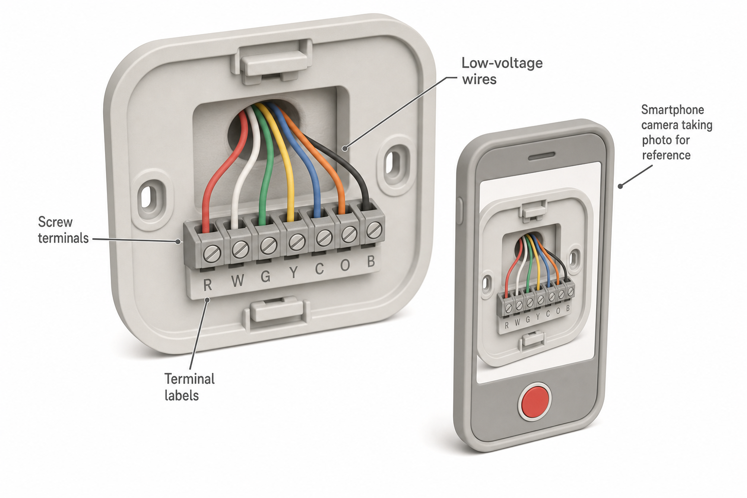
- Take a clear, well-lit photo of the wiring as it sits, close enough to read both the terminal letters printed on the plate and the wire colors.
- Write down each terminal letter and its wire color on a piece of tape or a notepad — for example: R = red, W = white, Y = yellow, G = green, C = blue. Don't assume color always matches function; previous installers sometimes used whatever wire was on hand.
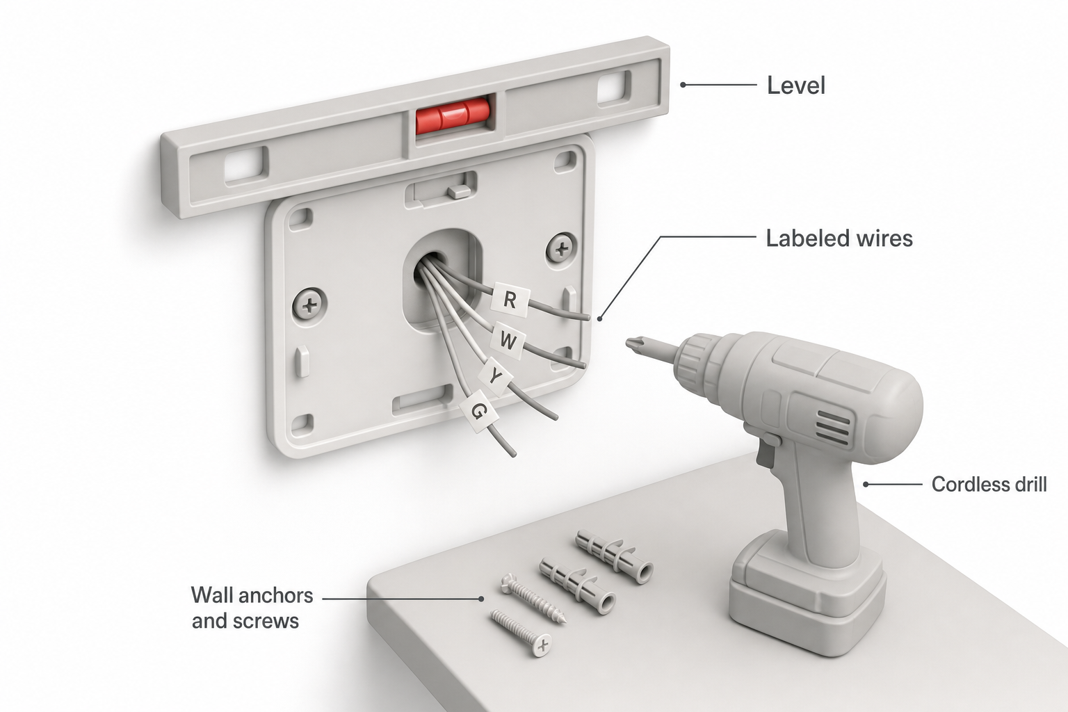
- Label each wire itself with small pieces of masking tape or the adhesive labels often included with new smart thermostats, writing the terminal letter directly on the tape wrapped around each wire. Do this before disconnecting anything.
- Note any terminals that are jumpered (a short wire or metal clip connecting two terminals, commonly R to Rc, or W to W2) — these jumpers matter for multi-stage or dual-fuel systems and need to be recreated or accounted for in the new thermostat's settings.
- Only after every wire is labeled and photographed should you loosen the terminal screws and free the wires from the old wall plate.
Common terminal letters and their typical roles:
- R (or Rc/Rh) — 24V power from the transformer (Rc for cooling, Rh for heating on some dual-transformer systems)
- W (or W1/W2) — heating call signal
- Y (or Y1/Y2) — cooling/compressor call signal
- G — fan
- C — common wire, providing continuous power to return current to the transformer (many smart thermostats require a C wire to power their screens and Wi-Fi radios)
- O/B — heat pump reversing valve (O typically energizes in cooling, B in heating, though this varies by manufacturer)
Step 4: Check Compatibility Before Mounting Anything
Most smart and programmable thermostat manufacturers provide an online compatibility checker where you enter the wires and terminal letters you found in Step 3. Run your labeled list through that checker before drilling any holes — it will flag missing C-wire situations or multi-stage configurations that need extra setup.
Step 5: Mount the New Backplate
- If the new thermostat's backplate doesn't cover old paint marks or screw holes from a differently-shaped previous unit, a wall plate or repositioning is often simpler than patching and repainting.
- Use a level to mount the plate — even small tilts are noticeable with sleek modern displays.
- If you're mounting into drywall without hitting a stud, use the wall anchors typically included with the thermostat; two screws is standard, but check the manufacturer's plate for exact hole spacing.
- Feed the labeled wires through the center opening before securing the plate, leaving enough slack to reach every terminal without tension.
Step 6: Connect Wires by Letter, Not Memory
Match each labeled wire to the identical terminal letter on the new thermostat — R to R, W to W, Y to Y, G to G, C to C, and so on. If your old system had multiple letters for one function (Y1/Y2, W1/W2) because of multi-stage heating or cooling, connect them in the same pattern unless the new thermostat's manual specifies otherwise for that configuration. Strip only enough insulation to seat fully in the terminal — about 3/8 inch (roughly 1 cm) is typical — and tighten each screw terminal snugly without overtightening, which can shear thin bell wire. If any jumpers existed on the old plate, recreate them per the new thermostat's installation manual, since many modern units handle multi-stage logic internally rather than through physical jumpers.
Step 7: Restore Power and Test Through a Full Cycle
- Snap or screw the display onto the backplate.
- Restore power at the breaker, then the furnace switch.
- Complete the manufacturer's setup process (Wi-Fi pairing, system type confirmation, schedule creation).
- Test heating: set the target temperature well above room temperature and confirm the furnace or heat pump ignites/runs within a few minutes.
- Test cooling (if applicable): set the target temperature well below room temperature and confirm the compressor and fan engage. Wait at least five minutes between switching from heat to cool to avoid short-cycling the compressor, a precaution many HVAC manufacturers recommend to protect the equipment.
- Test the fan-only setting if your thermostat offers one.
When to Call a Professional Instead
Consider bringing in a licensed HVAC technician or electrician if you encounter any of the following: a line-voltage baseboard heat system, wiring that doesn't match any standard letter/color pattern, a missing C wire with no clear path to add one, a heat pump with unusual multi-stage or auxiliary heat wiring you can't identify, or a furnace control board that looks damaged or scorched. These situations move outside straightforward thermostat swaps and into territory where the recommendations below for tools can help, but expertise matters more than equipment.
FAQ
Do I need a C wire to install a programmable thermostat? Not always — many basic programmable thermostats run on the power "stolen" from the call wires and don't need one. However, most Wi-Fi-enabled smart thermostats do require a C wire or an adapter to keep their display and wireless radio powered continuously.
What if my old thermostat has wires that don't match any letter I recognize? Stop and photograph everything, then check the manufacturer's documentation for both the old and new thermostats, or contact an HVAC technician — mislabeling can cause the system to run continuously or not at all, and in rare cases can damage the transformer.
Can I reuse the existing wall holes if the new thermostat is a different shape? Often yes, using a trim plate or cover plate designed to hide old screw holes and paint outlines, which many manufacturers sell alongside the thermostat.
Is it normal for the system not to respond immediately after installation? A brief delay of a few minutes is normal, especially for compressors protected by an internal delay timer. If nothing happens after 10–15 minutes, recheck your wiring against your labels before assuming a bigger problem.
Will installing my own thermostat void my HVAC warranty? This varies by manufacturer and by whether the thermostat is considered part of a bundled or "communicating" system; check your equipment's warranty terms, since some communicating systems require matched, professionally installed thermostats to maintain warranty coverage.